Welcome to the Gigatron!
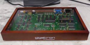
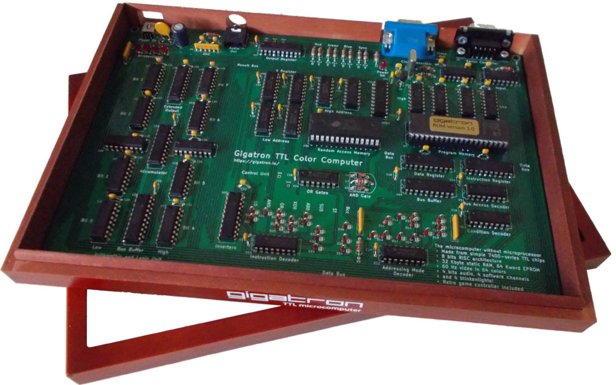
The Gigatron TTL microcomputer is a minimalistic retro computer. It’s special in its own oddball way, because it has absolutely no complex logic chips in it, not even a microprocessor! Its CPU is built out of a handful of classic 7400-series ICs, colloquially known as the TTL logic series. These chips combined form a powerful 8-bit processor.
Besides running applications, this processor performs functions that traditionally require dedicated peripheral chips for video, sound and other I/O. By eliminating these the hardware remains small and understandable. Still the single-board system works as a full-blown microcomputer that you can play video games with.
Now you can easily build one yourself. As you build, learn what happens inside a CPU by looking inside one. See the functional units, look inside the Arithmetic and Logic Unit, see its truth tables and learn what makes up a ROM. Then go on to enjoy playing the built-in retro video games or write little programs in BASIC. You can also hack it in any way you like if you have a taste for that.
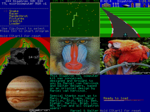
[Click on the image to enter the Gigatron emulator by Phil Thomas]