Mandelbrot from TTL

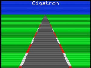
I got a bit stuck with the work I was planning for today, so I wrote something else to regain motivation: a fractal! Rendering takes a while, being fully interpreted and lacking multiplication, and even without the “right-shift” operation you badly need for this. All those must be mimicked with slow high-level code using just addition and subtraction.

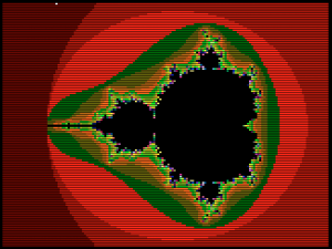
It should be easy to speed the whole thing up a lot just by adding a right-shift assembly function. Next time… GCL source code:

{-----------------------------------------------------------------------+
|                                                                       |
|       Mandelbrot fractal                                              |
|                                                                       |
+-----------------------------------------------------------------------}

gcl0x

{
  Plot the Mandelbrot set

  - 160x120 pixels and 64 colors
  - Faithful translation of mandelbrot.c pre-study
  - Use 16-bit vCPU math as 7-bit fixed point arithmetic (1.00 -> 128)
  - Implement multiplication in interpreter
  - Implement shift-right in interpreter as well
  - A bit slow (8242.655 seconds)

  XXX At the end change all to grey tones and redo
  XXX Redo at different sections
  XXX Tone for every pixel value
}

{-----------------------------------------------------------------------+
|                       RAM page 3                                      |
+-----------------------------------------------------------------------}
$0300:

{ Pretty accurate multiply-shift ((A*B)>>7), but it can be off by one }
[def
  push

  {Extract sign and absolute values}
  0 sign= C=
 {0}A- [if>0 A= 1 sign=]
  0 B- [if>0 B= sign 1^ sign=]

  {Multiply}
  7 shift= {Pending shift}
  $200
  [do
    bit=
    -$4000 C+ [if<0 C C+ C= else {Shift prematurely in an attempt to avoid overflow} B ShiftRight! B= shift 1- shift=] {Add partial product} A bit- [if>=0
      A=
      C B+ C=]

    bit ShiftRight! if<>0loop]

  {Shift}
  [do
    C ShiftRight! C=
    shift 1- shift= if>0loop]

  {Apply sign to return value}
  sign [if<>0 0 C- else C]

  pop ret
] MulShift7=

{ Calculate color for (X0,Y0) }
[def
  push
  0 X= XX= Y= YY= i=
  [do
    i 1+ i= 64^ if<>0           {Break after 64 iterations}

                                {Mandelbrot function: z' := z^2 + c}
    X A= Y Y+ B= MulShift7! Y0+ Y= {Y = 2*X*Y + Y0}
    XX YY- X0+                  X= {X = X^2 - Y^2 + X0}

                                {Calculate squares}
   {X}A= B= MulShift7!          XX=
    Y A= B= MulShift7!          YY=

    -$200 XX+ YY+ if<0loop] {Also break when X^2 + Y^2 >= 4}
  i
  pop ret
] CalcPixel=

{-----------------------------------------------------------------------+
|}\vLR>++ ret{          RAM page 4                                      |
+-----------------------------------------------------------------------}
$0400:

[def
  push

  $7ff p= {Start of video (minus 1 to compensate for 1st step)}

  -323 X0= 3 DX= 161 Width=  {Horizontal parameters}
  -180 Y0= 0 DY= 120 Height= {Vertical parameters}

  [do
    {Length of next segment, either horizontal or vertical}
    DX [if<>0 Width 1- Width= else Height 1- Height=] if>0
    [do
      len=

      {Step in the fractal plane}
      X0 DX+ X0=
      Y0 DY+ Y0=

      {Matching step in video frame}
      DX [if<0 p 1- p=] DX [if>0 p 1+     p=]
      DY [if<0 -$100 p+ p=] DY [if>0  $100 p+ p=]

      63 p. {White while busy here}

      {First check if we are inside one of the main bulbs for
       a quick bailout (Wikipedia)
       (x+1)^ + y^2 < 1/16}
      Y0 A= B= MulShift7! YY=
      X0 128+ A= B= MulShift7! YY+ 8- [if<0 0
      else

      {q*(q + x - 1/4) < 1/4*y^2, where q = (x - 1/4)^2 + y^2}
      X0 32- A= B= MulShift7! YY+ {q}
      A= X0+ 32- B= MulShift7! tmp=
      tmp+ tmp= tmp+ tmp= {*4} YY- [if<0 0 else {Otherwise run the escape algorithm} CalcPixel! ]] p. {Plot pixel} len 1- if>0loop]

    DY tmp= DX DY= 0 tmp- DX= {Turn right}
    loop]
  pop ret
] CalcSet=

{-----------------------------------------------------------------------+
|}\vLR>++ ret{          RAM page 5                                      |
+-----------------------------------------------------------------------}
$0500:

{ Stupid shift-right function }
{ XXX Better make a SYS extension for this }
[def
  a= 0 b=
  $8000 a+ [if>=0 a= $4000 b+ b=]
  $c000 a+ [if>=0 a= $2000 b+ b=]
  $e000 a+ [if>=0 a= $1000 b+ b=]
  $f000 a+ [if>=0 a= $0800 b+ b=]
  $f800 a+ [if>=0 a= $0400 b+ b=]
  $fc00 a+ [if>=0 a= $0200 b+ b=]
  $fe00 a+ [if>=0 a= $0100 b+ b=]
  $ff00 a+ [if>=0 a= $0080 b+ b=]
  $ff80 a+ [if>=0 a= $0040 b+ b=]
  $ffc0 a+ [if>=0 a= $0020 b+ b=]
  $ffe0 a+ [if>=0 a= $0010 b+ b=]
  $fff0 a+ [if>=0 a= $0008 b+ b=]
  $fff8 a+ [if>=0 a= $0004 b+ b=]
  $fffc a+ [if>=0 a= $0002 b+ b=]
      a 2& [if<>0          b<++ ] b ret ] ShiftRight= {-----------------------------------------------------------------------+ |}\vLR>++ ret{          RAM page 6                                      |
+-----------------------------------------------------------------------}
$0600:

{ Main }
[do
  CalcSet!
  60 \soundTimer. {For debugging}
  loop]

{-----------------------------------------------------------------------+
|       End                                                             |
+-----------------------------------------------------------------------}

– Marcel

CBA Podcast

As I mentioned in the previous post, I did a talk about the Gigatron at the RevSpace hackerspace. One of the people there was Michai, who has a podcast called CBA podcast, about software, electronics and mechanics. He mentioned the talk in his latest podcast (from 6’41).

– Walter

Another hackerspace lecture

Last friday, I gave another lecture about the Gigatron at a hackerspace, this time at Revspace. We got some really good feedback and it was very nice to talk to people that have been working on building their own processor or computer.

The lecture was not recorded, but an earlier version of the talk, that was given a month ago at the Hack42 hackerspace, is. It is included here.

– Walter

930 Logic gates

While playing Gigatron Snake at 34C3 we got asked: “how many gates are in there?”. This isn’t the first time someone has asked, so today I finally went through the TTL datasheets and counted little blocks from their logic diagrams. TL;DR: the CPU has 930 logic gates.

And because 34C3 is such an inspiring place, after one day of hacking those gates now happily animate this beginning of a Racer game:

Gate counting isn’t as straightforward as it seems though. RAM and ROM are clear: they each have thousands of logic gates in their word line decoders alone, but those aren’t part of the CPU proper. The clock isn’t part of the CPU either, but that’s just a couple of inverters. For decoding the game controller it isn’t as clear cut: the kit version has a 74HC595 shift register which has roughly 80 gates. But only 10 buffer gates are really needed by the CPU and are directly controlled by it. I fact, on the breadboard version, the input chip is just a 10-gate 74LS244 non-inverting buffer. So I count that as one 10 for the CPU. I also didn’t count the “extended output” register as part of the CPU because that is an extension on top of its primary output.

I did include all other gates that are in the IC packages: An unused module is in the count (there is one unused decoder in the control unit), as well as gates that are hooked to fixed inputs (L or H), even though all of those can be optimised away in VHDL. The 4-bit adders each have 4 non-inverting buffers internally that have no logic function, but I still include them. Furthermore, I count D-type flipflops as 5 gates, and SR-types as 4. Still, the total gate count of 930 is a lot lower than I would have guessed.

– Marcel

Manual

We are in the process of turning the Gigatron in a kit that can be built by others. For this, I’ve made a full-colour booklet that contains a generic explanation about the electronic components used, a crash course in soldering and the actual instructions to build the Gigatron. It includes many pictures and describes how to perform tests during the building process. In the appendix, you will find the full hardware schematics.

Gigatron manual

With this manual, even less experienced people should be able to build their own Gigatron.

– Walter

Tail chasing its head

To make 64 colors, every pixel occupies 6 bits of a byte in RAM. The two high bits can have arbitrary values as they are masked by the pixel burst loop. This opens up all kinds of tricks. For example, they can encode play field information for a game: where there are walls, independent of their color. Here I use these bits in the snake segments: they keep track of direction so the tail can follow the head. Like invisible breadcrumbs. Up/down/right/left just needs 2 bits…

– Marcel

SYS calls for accelerating interpreted programs

The virtual CPU or interpreter is now complete. At least, its code page is full, even overflowing a bit, and nothing can be added without removing something else. It has 25 opcodes, the last added is SYS. This is an escape: with SYS the application can jump to arbitrary native code. Here I test this capability in the “clear screen” loop, right at the beginning of the recording.

Without acceleration, clearing the screen pixel by pixel with interpreted code takes more than 2 seconds. Here the application uses a SYS call that clears 8 pixels at a time. The result is that the screen now clears in 200 ms. Nice proof of concept.

Restrictions apply if you don’t want to break the video timing: the callee must be timing-aware and cooperate with the interpreter loop. But it can run for longer than a regular vCPU instruction (these are 28 cycles max) and the code can do whatever it wants, as long as it completes in the available time slice on the scan line. In reality this means that SYS calls can last for up to 146 cycles. If they need more cycles, they could still use some trickery and restart themselves by messing with the virtual program counter… They are “parasitic” after all.

Another novelty is that this recording is not from an actual Gigatron! Martin @ the talkchess forum has made an incredible visualisizer for the project. I didn’t get it running with the Mac binary, but it runs ok with Wine. Emulation in emulation in emulation, but it can still keep up with real time if you use “Run sketch (JIT)”. Amazing.

There is some latency with the sound, but that is fine. This tool already saved me a tons of EPROM burning cycles. For the real experience, just use a real Gigatron…

P.S: The Christmas card is there to give my phone something to focus on. Without it the recording is blurry.

– Marcel

The Gigatron as a kit!

(Taken from https://hackaday.io/project/20781/log/71293-gigatron-the-ttl-computer-as-a-kit)

Some months ago my good friend Walter has silently joined the project. The reason is that I receive a lot of enthusiasm whenever I show this to friends, to the point where one is already seriously trying to write a chess program for it. So we decided to take this one step further and upgrade this to a build-it-yourself soldering kit. Today we received the first samples for the enclosure, custom designed for this computer.

With a new phase comes a new name. Neither of us really liked the “Chipper” working title I used before, so the kit version will be known as the “Gigatron TTL microcomputer”. I couldn’t possibly do this alone, so I’m super happy that Walter has stepped in.

This retro-computer is something to build, play with but also look at, so we plan to offer it as complete as possible, except for the soldering you will have to do yourself. So it will include all the 74xx-TTL chips, RAM, ROM, sockets, capacitors, diodes, resistors, LEDs, supervisory circuit, jacks, a game controller, a nice mahogany coloured wooden enclosure with plexiglass viewing window, one or two built-in video games and a mini-USB cable for power. Not all details are finalised yet: the photo is a prototype and we will still change some things we don’t like. We think we can target the 150-180 euro price range (hopefully below 200 dollars), provided there is sufficient interest. For reference, getting to the first PCB version set me back north of 500 euros, that is where I stopped counting, and that excludes the oscilloscope you need when designing something like this from scratch and 800 hours of research, trial and error. This is still just a private hobby project, so this kit will be something we will literally do from our living rooms. We figure that if we do a few dozen units that would push the prices down a lot and at the same time not take too much risk.

Of course a kit isn’t the same as a one-off project, and Walter has worked tirelessly on morphing the project towards something that can be reliably soldered together in 3 to 4 hours. All components are now through-hole components and sourced from proper sources (not scavenged from e-bay). Walter has written a supercool manual that includes intermediate tests, a circuit diagram and even soldering instructions and tips for novices. Although there are 144 components on the board (many capacitors and diodes), I feel it will still be a beginner’s level kit because of the spacing and all through-hole components. All you need is a soldering iron, solder, a multimeter, some pliers and a rainy Sunday afternoon. If you can make Oscar’s PiDP-8, then you can make this also.

For those interested in this kit, you can subscribe to our mailing list. We will use this mailinglist only to announce when we are comfortable to accept orders, know the exact pricing and have some kits ready to ship. Subscribing to the mailing list doesn’t imply any obligation to buy: it is just a way to keep informed of when we are ready and you can easily delist as well. We expect we will be ready near the end of January. It will then also be clear what the final kit looks like, what the built-in software can do, etc.

– Marcel.